SebPS

OUTLINE

Beginning year 11 my electronics workbench was quite decked out; the only thing missing was a decent DC power supply. Reading around online, good ones with decent range and constant current capability were going to set me back at least 150$ (quite a lot for the cash-strapped student I was!); so I decided to make one.

After a few weeks of spending the odd school afternoon perfecting prototype circuits, simulating, and slowly piecing a master-circuit together, I had a working schematic.The following weekend I layed out a PCB in EAGLE and sent it off to iTead Studio to get manufactured. When the board had finally arrived, I ordered all of the components from Element14 (which were shipped and arrived the next day surprisingly) and assembled the thing (a process that took a little less than half a day – which included using the dremel to cut out panel holes etc).

Amazingly, when I turned it on the first time to begin programming, the on-board chip was recognized and everything seemed to be working! I then stuck the firmware on there that I had developed intermittently whilst waiting for the board to arrive — there were a few bugs, but nothing that a couple of hours extra work couldn’t fix; except the devices current-readings were slightly out (A hardware issue, I have narrowed it down to resistor tolerances and will substitute a couple with potentiometers in the near future).

The circuit

dpscircuit

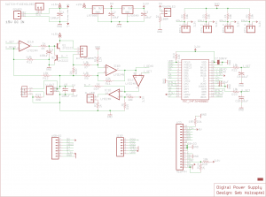
(you probably want to follow the image link twice to view it properly)

Running along the top isn’t all that interesting, we have on the left the sockets for the DC input and fuseholder alongside some bypass capacitance for stability. Then we have 2 regulators; a 5v for the LCD, and a 3.3v for the microcontroller. Followed by this we have a little subcircuit for the power LED, then four buttons with pull-down resistors.

The majority of the analog+interesting circuitry lies mid-left of the schematic. 0-3.3v RC-filtered PWM from the microcontroller enters V_SET and IC1A, which drives two transistors in a darlington configuration, a smaller 2n2222 (Q1) followed by a higher-power heatsinked 2n3055 (EXT). IC1A is set up as an amplifier whereby feedback comes from the darlington’s output and is divided so that 12v scales to 3.3v (also read by V_READ). This has the effect that 0-3.3v from the micro corresponds to an adjustable 0-12v at up to 1 amp across V_OUT. Notice that Q2, when turned on, will zero the voltage output as it switches off the darlington pair – this is used for current limiting which is explained later.

R8 is the 0.5 ohm current-sense resistor, the voltage-drop is amplified by IC1B in a differential-amplifier configuration whereby 0-0.5v sensed corresponds to 0-3.3v being output.This is then sent straight back to the micro through I_READ, and also compared (by an op-amp acting as a comparator) with I_SET in IC1C. The output of this is fed into the base of Q2 (described earlier), which consequently means that current is limited according to the voltage output by the micro at I_SET. The output of IC1C is also compared with a fixed, relatively low voltage and directly drives a ‘current limiting active’ LED.

The last part of the analog circuitry lies around V_OUT. To the right is some bypass capacitance, and to the left is a constant-current sink IC (LM334Z) configured to run at 1mA. This was required as in my breadboarding tests the circuit was unstable at currents under ~200 microamps. The offset this causes to the current reading is negated in software.

The other parts of the circuit are mostly digital, the micro and its boilerplate components as well as the lcd, some programming headers and an IO expansion header.
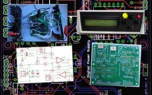
Construction

The PCB was designed to fit inside a Hammond model 1598BSGYPBK case (from specification as I didn’t actually have the case at the time), mounted with 6 screws. When the case arrived, I soldered the components onto the PCB, mounted the rear power transistor and heatsink, cut out panel holes with a drill and dremel and then gradually pieced the thing together.

Pricing

Overall, the project cost me somewhere in the region of 140$, but this figure is inclusive of unused components as well as the 11 other copies of the PCB I ordered (12 is the minimum order, for a cost of about 40$) and a 30$ 15v 2amp power-pack from the local Jaycar store.

As the components totalled ~70$, I could have easily wiped off 30$ by ordering from a larger distributor (i.e digikey) and not ordering any excess components. Also, with the manufacture of more than one unit, the PCBs would have only cost ~3$ each. The powerpack can probably be purchased off of Ebay significantly cheaper also (lets say 20$). Considering these changes, individual units could quite realistically be built for somewhere around 55$ – a lot less than the 150$ item that I had originally considered for purchase.

All in all, I ended up spending about the same amount of money I would have spent had I simply a purchased a proven supply. The learning experience that accompanied my route however, I believe has strengthened my electronics background quite reasonably.

4-bit Pic24 Alphanumeric LCD library

Looking all over the internet, I could not find for the life of me any existing Alphanumeric LCD library for the C30 compiler – so I made one, which requires 6 pins to operate. It only has 3 commands; lcd_print, lcd_command and lcd_init. For printing anything more complex than a string, the standard library can be included and sprintf is used to format a temporary string to be sent the LCD’s way. Files here are tested on a PIC24FJ64GB002, MPLAB X 1.10, C30 3.30c.

An example main.c file – Flashes an LED while displaying a switch position and ADC reading on an LCD:

#include "setup.h"
#include "lcd.h"
#include <stdio.h>
 
// Configuration setup
_CONFIG1( FWDTEN_OFF & GWRP_OFF & GCP_OFF & JTAGEN_OFF & ICS_PGx3 )
_CONFIG2( FCKSM_CSDCMD & OSCIOFNC_ON & POSCMOD_HS & FNOSC_FRCPLL & I2C1SEL_PRI & PLL96MHZ_ON & PLLDIV_NODIV & IESO_OFF & IOL1WAY_OFF );
_CONFIG3( SOSCSEL_IO );
 
int main() {
    // Set the LED pin to an output
    TRISBbits.TRISB7 = 0;
 
    // Set the switch pin to input
    TRISBbits.TRISB8 = 1;
 
    lcd_init();
 
    //Initialize ADC
 
    AD1PCFGbits.PCFG9 = 0; // Enable analog pin 9
 
    AD1CON3bits.ADCS = 0b00111111; // Set ADC clock to 64 x Tcy
    AD1CON1bits.SSRC = 0b111; // Auto-conversion on
    AD1CON3bits.SAMC = 0b00011; // Time bits = 3 TAD
 
    AD1CHS = 9; // Use positive input 9 on channel 0, relative to Avss
 
    AD1CON1bits.ADON = 1; //Turn on ADC
 
    char final[32];
 
    while(1) {
        lcd_command( LINE1 ); // Print out the switch status
        lcd_print( "Switch: " );
        lcd_print( (PORTBbits.RB8 == 0)? "On  " : "Off  " );
 
        lcd_command( LINE2 ); //Print out the voltage on A9
        AD1CON1bits.SAMP = 1;
        while( !AD1CON1bits.DONE );
        float voltage = ((float)ADC1BUF0 * 3.3f)/1024.0f;
        sprintf( final, "Voltage: %3.2f  ", voltage );
        lcd_print( final );
 
        LATBbits.LATB7 = ~LATBbits.LATB7; //Toggle an LED
 
        __delay_ms( 100 );
    }
}

The library (and the example main file given) needs a setup.h file to be declared with some includes. I didn’t put the device configuration bits in here, otherwise there’s a linker error:

// Includes some commonly used libraries, sets device configuration,
// defines some useful things.
 
#ifndef SETUP_H
#define SETUP_H
 
#include "p24Fxxxx.h" // This header will choose the right device header
 
#define FCY 16000000UL // Running at 16 MIPS = Fosc/2
 
#include <PIC24F_plib.h>
#include <libpic30.h>
 
// Define a C++-like boolean - makes things more readable in some cases
typedef unsigned bool;
#define true 1;
#define false 0;
 
#endif

Here’s your lcd.h code:

// (c) Seb Holzapfel, 2012
// A 6-pin Alphanumeric LCD interface library
 
#ifndef LCD_H
#define LCD_H
 
#include "setup.h"
 
// Change these to the pins you want
#define LCD_RS_PIN LATBbits.LATB0
#define LCD_E_PIN  LATBbits.LATB1
#define LCD_D4_PIN LATBbits.LATB2
#define LCD_D5_PIN LATBbits.LATB3
#define LCD_D6_PIN LATBbits.LATB4
#define LCD_D7_PIN LATBbits.LATB5
 
#define LCD_RS_TRIS TRISBbits.TRISB0
#define LCD_E_TRIS  TRISBbits.TRISB1
#define LCD_D4_TRIS TRISBbits.TRISB2
#define LCD_D5_TRIS TRISBbits.TRISB3
#define LCD_D6_TRIS TRISBbits.TRISB4
#define LCD_D7_TRIS TRISBbits.TRISB5
 
// LCD Command set
#define LINE1       0x80    // Set display to line 1 character 0
#define LINE2           0xC0    // Set display to line 2 character 0
#define FUNCTION_SET    0x28    // 4 bits, 2 lines, 5x7 Font
#define DISP_ON         0x0C    // Display on
#define DISP_ON_C       0x0E    // Display on, Cursor on
#define DISP_ON_B       0x0F    // Display on, Cursor on, Blink cursor
#define DISP_OFF        0x08    // Display off
#define DISP_CLR        0x01    // Clear the Display
#define ENTRY_INC       0x06    // Increment-mode, display shift OFF
#define ENTRY_INC_S     0x07    // Increment-mode, display shift ON
#define ENTRY_DEC       0x04    // Decrement-mode, display shift OFF
#define ENTRY_DEC_S     0x05    // Decrement-mode, display shift ON
#define DD_RAM_ADDR     0x80    // Least Significant 7-bit are for address
 
#define LCD_DATA_MODE 1
#define LCD_COMMAND_MODE 0
 
void lcd_command( unsigned command );
 
void lcd_print( char text[] );
 
void lcd_init();
 
#endif

And the lcd.c file:

// (c) Seb Holzapfel, 2012
// A 6-pin Alphanumeric LCD interface library
 
#include "lcd.h"
#include <string.h>
 
inline void lcd_toggle_enable() {
    LCD_E_PIN = 1;
    LCD_E_PIN = 0;
}
 
void lcd_mode( unsigned mode ) {
    LCD_RS_PIN = mode;
    __delay_us( 100 );
}
 
void lcd_clock_nibble( unsigned char nibble ) {
 
    // Set data pins according to bitmask
    LCD_D4_PIN = ((nibble & 0b1   ) > 0);
    LCD_D5_PIN = ((nibble & 0b10  ) > 0);
    LCD_D6_PIN = ((nibble & 0b100 ) > 0);
    LCD_D7_PIN = ((nibble & 0b1000) > 0);
 
    // Clock them
    lcd_toggle_enable();
}
 
void lcd_clock_byte( unsigned char byte ) {
    lcd_clock_nibble(byte >> 4);
    __delay_us( 50 );
    lcd_clock_nibble(byte);
    __delay_us( 50 );
}
 
void lcd_print( char text[] ) {
    // Incrementing pointers and checking for null doesn't work for some reason
    unsigned l = strlen(text); // So I used the inbuild length function.
 
    lcd_mode( LCD_DATA_MODE );
 
    unsigned i; // Declaration outside because we're not in C99 mode.
    for( i = 0; i != l; ++i ) {
        lcd_clock_byte( text[i] );
    }
}
 
void lcd_command( unsigned command ) {
    lcd_mode( LCD_COMMAND_MODE );
    lcd_clock_byte( command );
    __delay_ms(2); // Wait a bit, some commands take a while
}
 
void lcd_init() {
    __delay_ms( 20 );
 
    // Set all LCD pins to output mode
    LCD_RS_TRIS = 0;
    LCD_E_TRIS  = 0;
    LCD_D4_TRIS = 0;
    LCD_D5_TRIS = 0;
    LCD_D6_TRIS = 0;
    LCD_D7_TRIS = 0;
 
    LCD_E_PIN = 0;
 
    // Enter command mode
    lcd_mode( LCD_COMMAND_MODE );
 
    // Initialisation sequence
 
    // Clock 0x03 twice
    lcd_clock_nibble( 0x03 );
    __delay_ms( 5 );
    lcd_clock_nibble( 0x03 );
    __delay_us( 200 );
 
    // Enter 4-bit mode
    lcd_clock_nibble( 0x03 );
    __delay_us( 200 );
    lcd_clock_nibble( 0x02 );
    __delay_ms( 5 );
 
    // Set up some defaults
    lcd_clock_byte( FUNCTION_SET );
    lcd_clock_byte( DISP_OFF );
    lcd_clock_byte( DISP_ON );
    lcd_clock_byte( ENTRY_INC );
    lcd_clock_byte( DISP_CLR );
    lcd_clock_byte( LINE1 );
 
    __delay_ms( 5 );
}

Use my code for whatever you like (hobby use, commercial use, whatever) – If you use it for something interesting, be sure to let me know!