Get the source here. Make sure to compile with ‘ghc fdtd -O2′ otherwise it’ll be insanely slow (Will be profiling for space leaks, probably switching to discrete array constructs in the future).
BBB Scopeclock conversion - Part 1
A few weeks ago, I came across an article on Hackaday about memory mapped IO, and the sorts of toggle speeds you can achieve on the Beaglebone’s output pins when using this technique as opposed to just using the file access API. Around the same time, I was reading some articles on Pulse Density Modulation (as opposed to Pulse Width Modulation) for another project I was working on; in an attempt to increase the slew rate of a low-pass filter on the output of a microcontroller I was using.
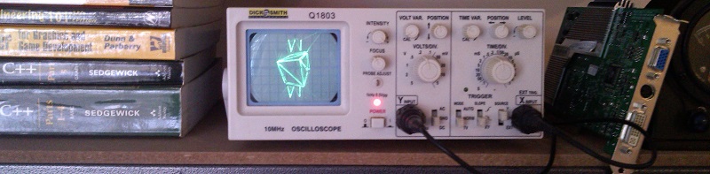
As it happened, I’d had this old Dick Smith scope laying around ever since I bought a DSO to replace it:- (Dick Smith have since stopped selling hobbyist electronics products, heh). And so I wondered if it would be possible, using a Beaglebone Black; to turn this old thing into some sort of clock with the X-Y mode as a vector display; using nothing but 2 toggling GPIO pins and a few passive components.
The Setup
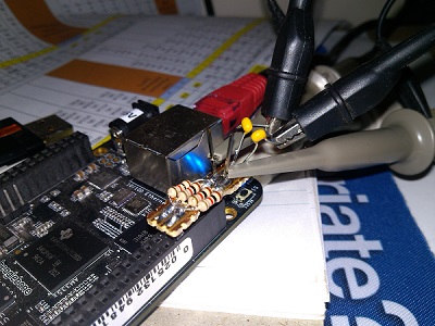
As you can see, there really isn’t much to it component-wise! The devil was much more so in the software for this project. I used a couple of bits of veroboard; some 1K resistors and 100nF caps. Input from the sixth GPIOs down from the right and left side of the right header, output straight to the X and Y inputs of the scope. Using:
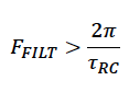
We can see our filter frequency will end up around (2pi)/(0.1μF500Ω)= 126KHz; so as long as we’re toggling at a rate considerably above that frequency; the output should be a relatively nice representation of the analog information we’re trying to create artificially. (A much more detailed workthrough of calculations can be found here)
The Software
Now for the difficult part: actually getting those pins to generate some meaningful signals. There were a few features I wanted from the get-go:
- Have some sort of interesting 3D animation while the time is displaying
- Be able to do everything fast enough so that I don’t need to blank the scope, as it doesn’t have a blanking input!
- Use Roman Numerals to represent the time (Eh, personal preference)
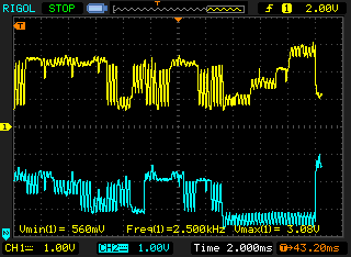
The first step was basic – getting the pulse-density-modulation down. I ended up smashing a couple of libraries together, namely BBBioLib (for fast, memory-mapped IO) and some PDM code derived from here. To test the system out, I just set up a loop from zero to max PDM value; in an attempt to generate a sawtooth:
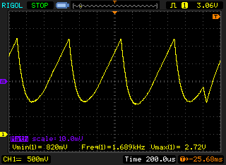
I’m pretty sure the artefact on the right is just the OS deciding to do something else; but for the most part; this waveform looked pretty good! Just had to bring the filter frequency up a bit to avoid some excess smoothing at the low-end. (Note: at this time I was using a decade resistance box; 500 ohm was the final value I decided on)
I then went ahead and modified a previous software project of mine, (basically the skeleton of a 3D renderer from scratch); to instead pipe the output points straight out the GPIOs. Initially, my approach had simply been to take the ends of lines and draw them across the screen of the scope. However, this didn’t really work as the scope spent just as much time seeking the start/end positions of lines as it did actually drawing them – the screen was just a mess of lines! My solution? Basically, instead of:
void Plot::DrawLine( Vec2 p1, Vec2 p2 ) {
    SetCoord(p1);
    SetCoord(p2);
}
Just draw back and forth a few times on the lines:
void Plot::DrawLine( Vec2 p1, Vec2 p2 ) {
    for(int i = 0; i != 4; ++i ){
        SetCoord(p1);
        SetCoord(p2);
    }
}
Which gives us:
(As you can see from the diagram the sections of waveform that are the same amplitude are line segments) – Meaning that the scope spends much more time on the actual lines, and much less time seeking them. Here’s what the output looks like in X-Y mode:
Now all that had to be done was the time displaying. For the roman numerals, things weren’t too complicated; I just filled some arrays full of coordinates for lines in the characters:
std::vector< t3::Vec2 > lines_x;
lines_x.push_back( t3::Vec2(0, 0) );
lines_x.push_back( t3::Vec2(5, 8) );
lines_x.push_back( t3::Vec2(5, 0) );
lines_x.push_back( t3::Vec2(0, 8) );

std::vector< t3::Vec2 > lines_i;
lines_i.push_back( t3::Vec2(2.5, 0) );
lines_i.push_back( t3::Vec2(2.5, 8) );
...
And then draw them at offsets determined by their position in a converted roman string taken from integer portions of the current time:
void DrawLines( std::vector< t3::Vec2 > &lines, t3::Plot &plot, t3::Vec2 offset ) {
    for( int i = 0; i != lines.size()/2; ++i ) {
        plot.DrawLine( lines[i*2]+offset, lines[i*2+1]+offset, ' ' );
    }
}

...

//(Part of DrawRomanNumberAtOffset)
        std::string roman1 = int_to_roman(num);
    for( int i = 0; i != roman1.size(); ++i ) {
        t3::Vec2 offset(20+7*i-roman1.size()*3, offset_y);

        if( roman1[i] == 'X' )
            DrawLines( lines_x, p, offset );
        else if ( roman1[i] == 'I' )
            DrawLines( lines_i, p, offset );
        else if ( roman1[i] == 'V' )
            DrawLines( lines_v, p, offset );
        else if ( roman1[i] == 'L' )
            DrawLines( lines_l, p, offset );
    }

... i.e:
DrawRomanNumberAtOffset( timeinfo->tm_min, 0, p);
Here’s a video of the roman numbers being displayed on top of the 3D rendering (Time delta sped up in software):
I actually came across a pretty strange problem with the Beaglebone’s built in timekeeping when writing the software; whenever I ran my application the time would just stop incrementing! I’m talking:
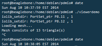
Now you can see that the system time has incremented 6 seconds, but I in fact had my application open for at least a minute! I’m still not quite sure what was going on there; but in software this meant that the clock would always be stuck on whatever the time was when the program was first executed. My fix was to fetch the unix epoch time, and increment it based on the CPU realtime clock before fetching the raw time every refresh. This meant the system time was still out of wack; but at least the clock functioned correctly.
That’s it for now! You can fetch the code here (2 binaries are included if you want to run it straight away; to compile it you’ll need to set up & install BBBiolib then run the build script). A lot of it is self-confessed hackjob; but I was strapped for time on this project :P
In my next post; I’ll probably be shoving the beaglebone in the scope and connecting it permanently.