 About a month ago I was frothing over a datasheet for a (pretty expensive) PLL synthesizer by Analog Devices, the ADF5355. It's capable of spitting out signals from 50MHz to 13.6GHz - widest I've seen!. It's got a VCO parked between 3.4 and 6.8GHz and internal dividers & doublers. Naturally, I requested some free samples of the $100 AUD (!!) part, to evaluate it - might be useful in a future project.
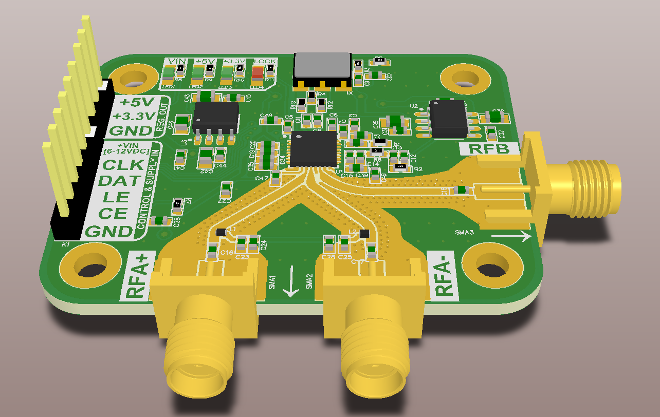
I then designed a board to house it - for a few reasons. Firstly, great practice for RF routing. Also, a good opportunity to create part in my EDA library so it's easier to use later on. Lastly, the official evaluation board was way too expensive for my student budget (~$600 each). Especially as I want to experiment with more than one!
Here's what I came up with:
And the schematic:
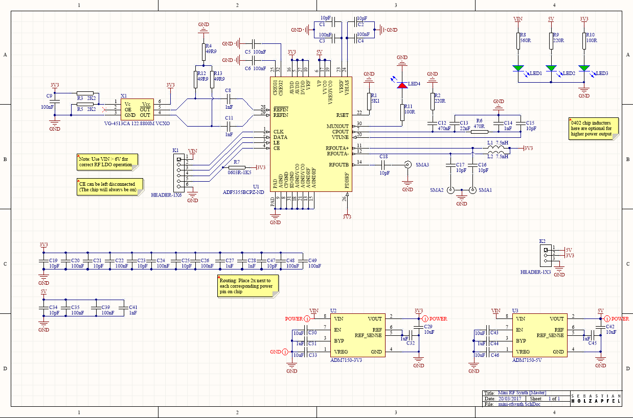
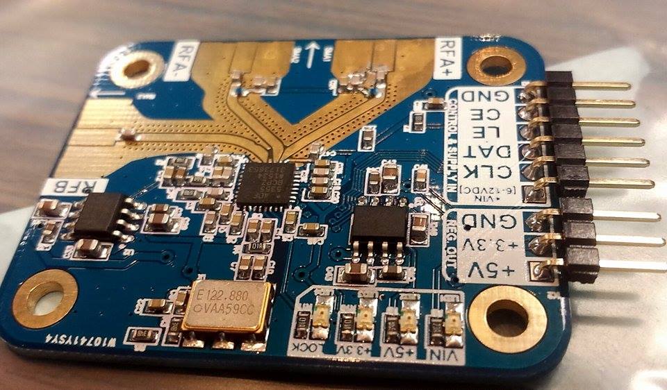
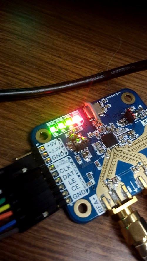
This is essentially as much as I was able to distill down the component count such that the device still works. Once I got the board, I started populating it (see first picture at the top of the post) - unfortunately, as happens more often than I'd like - there were some errors.
Take a look at this:
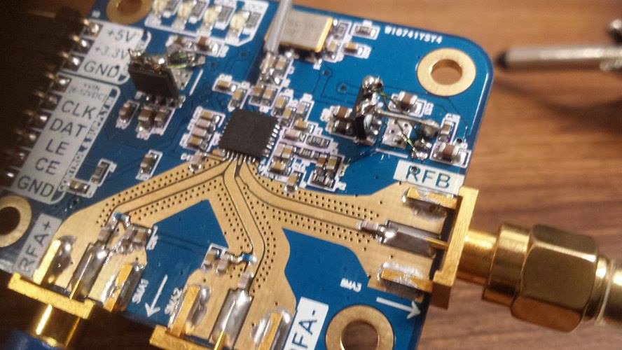
Yeah, pretty bodgy. Somehow, I managed to swap the pins on the linear regulator ICs, and the LVDS termination for the reference oscillator was slightly wrong. Hacking the board using some modwire fixed it up; and after spending a lot of time writing some C code to bit-bang SPI into the device I managed to get a lock (red LED):
Here's a picture of the setup on a (very messy) bench:
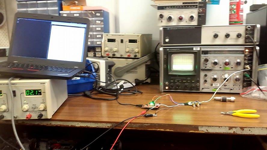
Lab PSU powering the PLL, Tiva Cortex-M4 spitting SPI into the PLL, and RFB (6.GHz+) connected to my HP 8555A spectrum analyzer. Hard to see the spike in the above picture, but it does work!
I then tried a more substantial experiment:
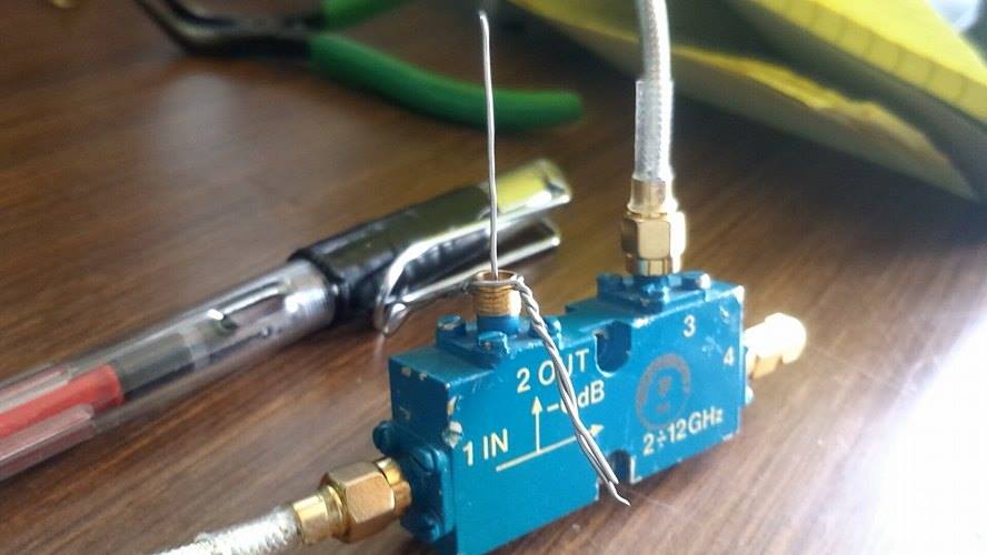
This is just a directional coupler. I've got the PLL at the input (1), a (dodgy handmade in 2mins) monopole-like antenna at the output (2), the spectrum analyzer at the reflected port (3) and a 50 Ohm dummy on forward (4).
I wrote a driver that does a sweep with the PLL across the frequencies near where I calculated the dodgy monopole should resonate at. Putting the analyzer's CRT persistance all the way up I got:
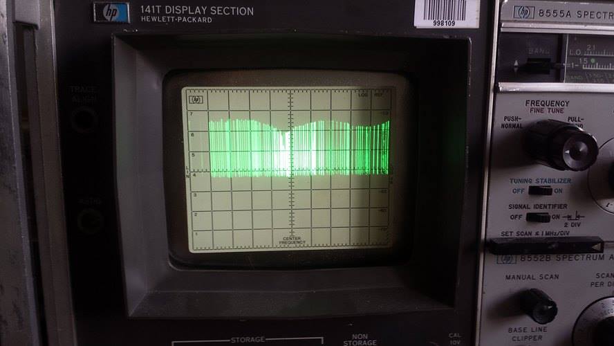
Sweet! obvious resonance around 2.2GHz, and the PLL seemed to sweep great.
I've fixed the errors with the schematic & board made in revision 1, more experiments coming soon!

