Analyzing the ugliest filter
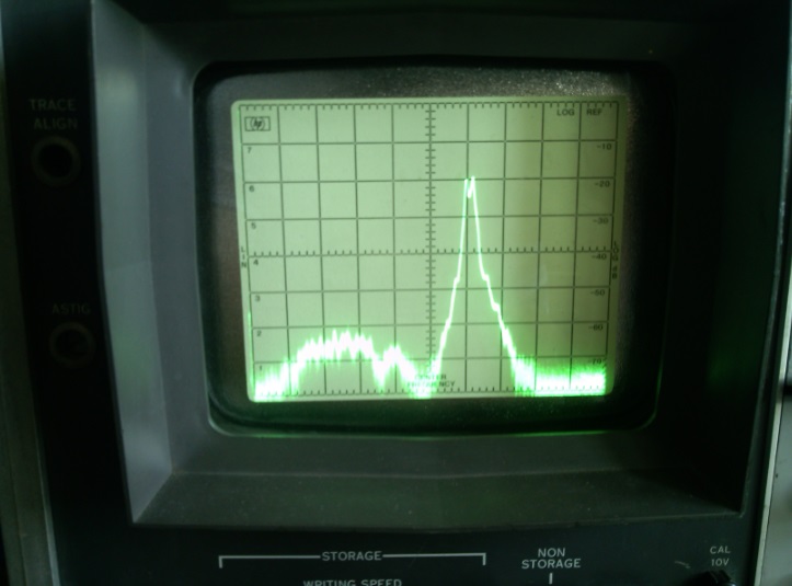
Or perhaps 'How to make a microwave filter for $0'. Yesterday afternoon I wanted a 1.2GHz filter for an experiment, didn't need anything super-performant, and didn't want to spend any money. Before I actually show you what the filter looks like (because it's hilariously ugly), here's it's response (0-2GHz sweep):
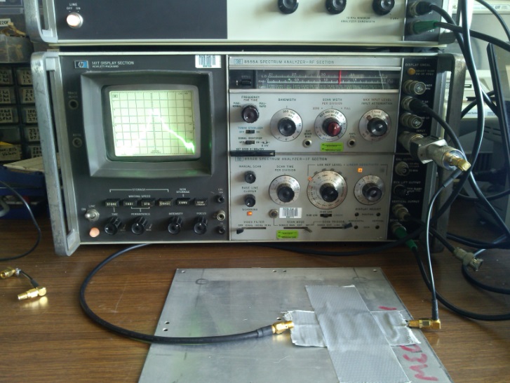
 Okay, the frequency response isn't so bad, but I'm putting -10dBm in so we've got about 10dB of insertion loss which isn't great. 300-600MHz seems to seep through at around -40dBc, which is surprisingly not bad. Here's the setup:
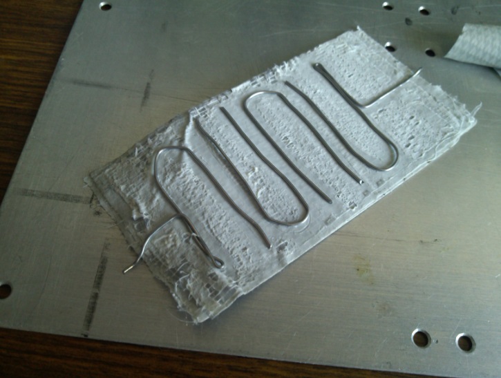
 So you can see from the tuning scale that the center is sitting around 1.2GHz (check out the header image), but what the heck is that thing on the table? To be honest, I'm actually surprised it works. Here's a picture of it taken apart (Note that the wires were bent more accurately before I took the device apart again and took this photo!):
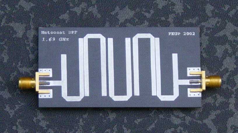
 Yep, some pieces of wire bent into shapes, stuck onto some tape with a sheet of aluminum used as a ground plane. This piece of MacGyver was suprisingly effective. If you aren't familiar with microstrip filters, what I've implemented is an extremely crude hairpin bandpass filter, which is usually supposed to look like this:
 Yep, the gods of RF strike again.