I have recently open-sourced my Eurorack-PMOD project, which is a collection of hardware and software to make it easier to get started in FPGA-based audio synthesis. Check it out here!
I have recently open-sourced my Eurorack-PMOD project, which is a collection of hardware and software to make it easier to get started in FPGA-based audio synthesis. Check it out here!
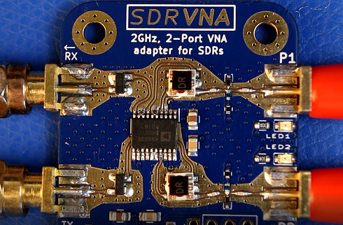
I thought it might prove an interesting challenge to attempt to use an off-the-shelf SDR (LimeSDR mini in my case), and build a 2Ghz-capable RF frontend for it to allow it to neatly do full 2-port characterizations of amplifiers and filters, like a true VNA, without having to wire up a bunch of external couplers.
The PCB I designed sits between the LimeSDR Mini and the device one wants to test:
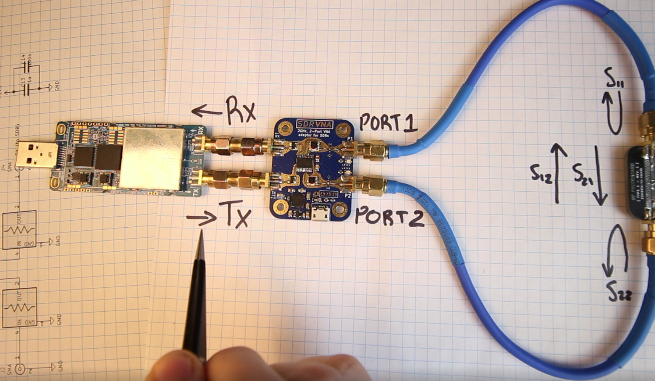
At a high level, the board has the following:
Given that the LimeSDR mini only provides a single RX and TX port, we're actually doing some shenanigans here to get full 2-port measurements. Ordinarily, VNAs contain more than one receiver (at least 2x RX channels), where one is used as some sort of amplitude + phase reference going into the DUT, and the other is used for receiving the test signal back from the DUT. Here, we can't do that, as we only have one RX channel! What do I do instead?
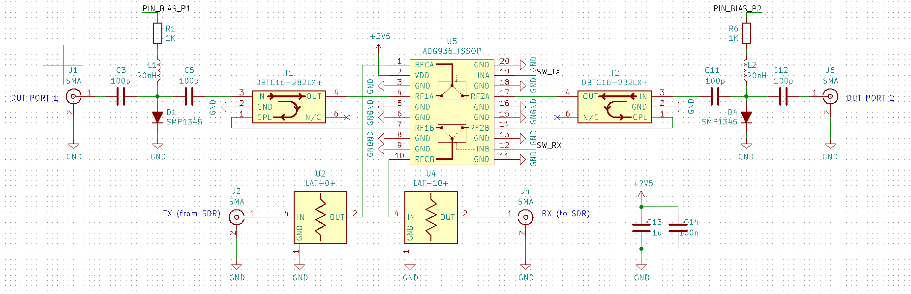
Here's how the VNA frontend works:
Even if we were to switch the excitation to each port as appropriate, we have nothing to compare the measurement to. The trick here to making do with only 1 RX channel (with the downside of introducing considerable error that needs to be calibrated out in software), is the PIN diode clamps close to the DUT ports.
The solution here is that the microcontroller (depending on the measurement mode) will turn the PIN diode clamps into reflecting shorts, periodically, at some duty cycle. The pattern of shorts/opens triggered at the diode clamps is detected by the software we use to demodulate the test signal (on the host Linux machine), and we can then establish the relative phase difference between the incident and returning signals. Bam, only one RX port (and a bunch of calibration) needed!
I haven't had a chance to clean up these repositories much yet, everything is truly in a state of just-working but for anyone who is interested, here they are: